Prototype de PCB en toute simplicité

Service complet de prototypage de PCB personnalisé.

Welding Capability

Part Sizes

Welding joins separate metal components by fusing material at mating joints. The process supports large size assemblies, and joint performance is affected by material thickness as well as the root gap between mating workpieces.

  • Min part dimension(flat):
    50 × 50 mm
  • Max part dimension(flat):
    10 m × 10 m
  • Material thickness lower limit:
    0.5 mm
  • Maximum root gap:
    10 mm
  • Minimum root gap:
    0 mm

Multiple Forming Technologies · On-Demand Matching

Precise · Clean
TIG Welding
TIG welding employs a non consumable tungsten electrode for controlled arc welding. It generates low spatter aesthetic weld seams and enables fine heat adjustment, ideal for cosmetic critical components with visible joint surfaces.
  • Precise heat control.
  • Clean, high-quality welds.
  • Suitable for stainless steel, aluminum, and other metals.
  • Excellent for thin gauge sheet and appearance focused parts.
Precise · Clean
TIG Welding
TIG welding employs a non consumable tungsten electrode for controlled arc welding. It generates low spatter aesthetic weld seams and enables fine heat adjustment, ideal for cosmetic critical components with visible joint surfaces.
Fast · Versatile
MIG Welding
MIG welding feeds continuous consumable wire electrode for continuous arc joining. It balances good mechanical strength and fast cycle times, widely adopted for general purpose structural sheet metal fabrications.
Precise · Low Distortion
Laser Welding
Laser welding applies highly concentrated laser energy as the heat source. Its narrow heat affected zone reduces workpiece warpage, making it well matched for delicate thin sheets and high precision intricate assemblies.

Available Materials For

In addition to the materials listed below, we also accept customer-supplied materials for processing.

Our Surface Finishes For Welding Parts

With our precision welding capabilities, sheet metal assemblies gain strong, reliable joints and a clean finished appearance,
built to meet demanding structural and functional requirements.

Standard (As-Milled) (Ra 125μin)
The finish option with the quickest turnaround. Sharp edges and burrs would be removed by default. (If you need parts with sharp edges and burrs, please remark below or note on 2D drawing). Surface finish is comparable to 125 uin Ra finish.
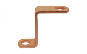
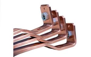
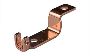
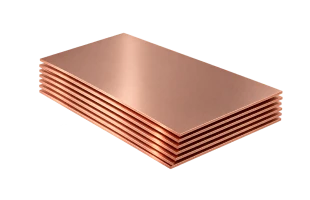
  • Copper C110
  • Stainless steel 304
  • Aluminum 5052
  • Copper 260 (Brass)

Standard (As-Milled) (Ra 125μin)

Bead blast + Anodized color

Anodized

Electrically conductive oxidation

Black oxide

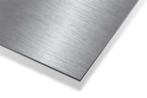
Brushed

Welding Capability

Process Description
Min part dimension(flat) 50 × 50 mm
Max part dimension(flat) 10 m × 10 m
Material thickness lower limit 0.5 mm
Maximum root gap 10 mm
Minimum root gap 0 mm

Welded Sheet Metal Parts Design Guidelines

This guide is designed to help mechanical engineers and product designers optimize laser-cut and bent sheet metal parts for welding processes. By adhering to Design for Manufacturability (DFM) standards during the CAD modeling stage, you can significantly enhance structural strength, eliminate thermal distortion, reduce assembly tooling costs, and shorten production lead times.


1. Allowed and Recommended Weld Joint Types

To ensure the mechanical strength of weld joints and effectively control heat input, we recommend using the following two standardized joint configurations:

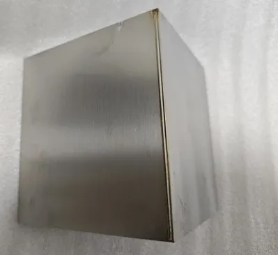
Corner Weld

Two bent edges meet at a 90° right angle.

  • Outside Corner Weld (Recommended): The welding torch is applied to the outside of the corner joint, yielding superior penetration, better fill, and a fuller weld appearance.
  • Inside Corner Weld: The welding torch is applied to the inside concave corner, suitable for applications with external assembly interference where weld protrusions are not permitted.


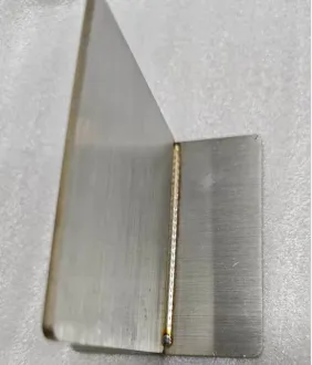
T-Joint Weld

One bent edge meets perpendicularly with the flat surface of another extending flange.

  • Also divided into Inside Fillet Weld and Outside Fillet Weld.
  • T-Joints offer excellent shear strength and are ideal for stiffeners, gussets, or baffle structures.

Unsupported Weld Types: Butt welds, lap welds, spot welds, stitch welds, and complex multi-part assembly welds are currently not available for standardized automated online quoting and processing, and require manual engineering review.


2. CAD Modeling & Design Rules

"Design for Bending First" Principle

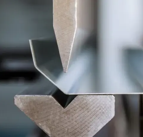
All welded parts must first satisfy standard sheet metal bending specifications. Design should complete 3D bend modeling first, as welding is a secondary process performed after bending. Always check clearance for bending tooling to prevent welding flanges from obstructing the bending stroke.


Do NOT Model Weld Geometry

Never draw fillet welds, weld beads, or weld cutouts in your CAD model. The model must reflect true, un-welded sheet metal bend geometry. The factory CAM system will automatically calculate weld compensation and joint normalization based on the selected material and thickness.


Bend Reliefs and Unsealed Corners

Laser welding is primarily used for structural connection and positioning alignment; it does not guarantee watertight or gastight seals. Bend relief gaps and open bend seams will not be automatically filled. If sealing is required, post-process sealant must be applied or manual full-fill grinding specified.


3. Innovative Features: Fixtureless Self-Alignment & Thermal Control Structures

To eliminate reliance on expensive welding fixtures and resolve thermal distortion issues in thin sheet metal welding, this guide introduces the following innovative DFM techniques:

Tab-and-Slot Self-Alignment Design

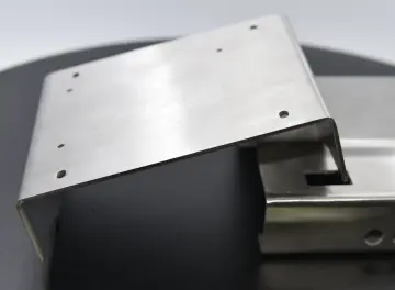
Incorporate interlocking tabs and slots directly into mating parts during the laser cutting phase.

  • Engineering Advantage: Parts achieve precise interlocking alignment without fixtures, eliminating cumulative assembly errors and manual measurement setup time.
  • Design Rule: Tab width is recommended to be 3x to 5x the sheet thickness, with a unilateral clearance allowance of 0.1mm~0.15mm.


Integrated Locating Holes and Alignment Pins

Place laser-cut locating holes(3.0mm~5.0mm)on non-welded datum surfaces to accept standard dowel/spring pins or locating bolts. This improves high-volume assembly consistency and serves as a inspection measurement datum.


Heat-Affected Zone (HAZ) Relief Cuts & Anti-Distortion Design

Thin sheet metal welding (e.g., 1.5mm aluminum alloy) is prone to "oil-canning" or wave distortion due to localized thermal expansion.

  • Stress Relief Slots: Incorporate elongated stress-relief slots in non-load-bearing areas adjacent to the weld to block thermal stress propagation across large flat surfaces.
  • Pulsed Laser Welding: Utilizing pulsed laser welding reduces the heat-affected zone to only 1/5 that of traditional TIG/MIG welding, drastically reducing residual stress while producing a visually appealing "stack-of-dimes" surface finish.


4. Finished Appearance, Delivery Expectations, and Post-Processing


5. Design Checklist

Please review and verify the following items prior to order submission or production release:

  • CAD Model Specification: Correct bending parameters have been applied to the part model, and no 3D weld beads or fillets have been modeled.
  • Root Gap: The assembly gap (root gap) at the target weld joint is controlled within 0.020'' (0.5mm) in CAD.
  • Self-Alignment Features: Tab-and-slot features or locating holes have been prioritized to reduce assembly and fixture alignment difficulty.
  • Torch Clearance: Weld locations avoid complex multi-bend intersections or tight internal enclosures, ensuring adequate torch accessibility and line of sight.
  • Coating Allowance: If powder coating or anodizing is required later, coating thickness allowances have been factored into mating tolerances (e.g., adding 0.05~0.1mm per side for powder coat).

Customer Reviews

Frequently Asked Questions

What welding methods do you offer?

Depending on the material, thickness, joint design, and application, welding methods may include TIG, MIG, laser welding, and spot welding.

When should I use welding instead of fasteners?

Welding is suitable when a permanent joint, higher structural rigidity, or a seamless appearance is preferred over removable mechanical fastening.

How can I reduce welding distortion?

Proper joint design, suitable material thickness, controlled heat input, appropriate welding sequence, and adequate fixturing can help minimize distortion.

What materials can be welded?

Common weldable materials include aluminum, stainless steel, mild steel, and other metals compatible with the selected welding process.

Can welded sheet metal parts be finished after welding?

Yes. Welded assemblies can undergo additional processes such as grinding, polishing, painting, powder coating, anodizing, or other surface treatments depending on the material.

Your files are in safe hands with us.
Start producing your project right away.

Get in touch with our team. Call us directly on. Or email us at 3dcnc@pcbway.com

Get instant quote

Full manufacturing capability at your fingertips