Holiday Notice: PCBWay factories will be closed on Sep 25, and Oct 1-4 (GMT+8). Orders can still be placed online during holidays, with extended lead times. Please place orders 3–5 days early to avoid delays. Read more >>


Prototype de PCB en toute simplicité

Service complet de prototypage de PCB personnalisé.

CNC Laser Cutting Services

Get a quote

Overview: How CNC Laser Cutting works?

The Basics Of CNC Laser Cutting

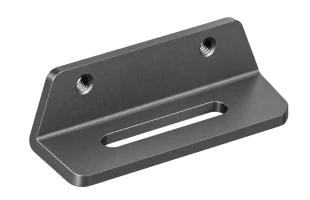
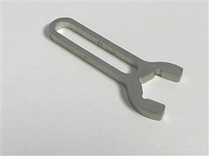
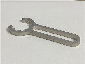
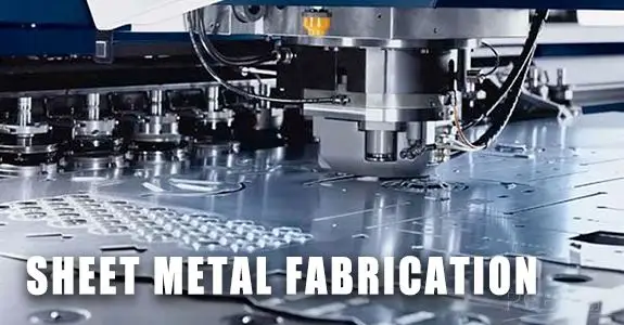
Laser cutting generates the first 2D flat of the sheet metal fabrication. Turnaround time for laser cutting is faster than punching, saving you time on shorter runs, and is more precise and consistent cut than mechanical cutting.


CNC laser cutting produces consistent clean edges to the most exacting tolerances. It is a flexible, versatile manufacturing solution for fabricating parts with complex geometries that require distortion-free finishes.

How Laser Cutting Works

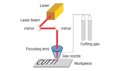
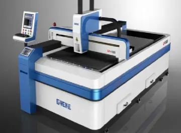
Laser cutting machines convert laser energy into extremely high amounts of heat by focusing a laser beam. This heat is enough to melt or vaporize metal. When the laser beam passes through the material, it creates a thin line on the metal surface. The production line is hot enough to cut the material.

How Laser Cutting Works

By manipulating the movement of the cutting head, the machine can complete cutting of complex shapes.


There are three types of laser cutting machines: CO2 laser cutting machines, YAG laser cutting machines and fiber laser cutting machines. Despite the different types, the working process of a laser cutter is relatively the same.

Features of CNC Laser Cutting

Advantages
Rapid Turnaround
The cutting speed is fast and the cutting speed is stable, which can realize cutting methods such as fast cutting and lightning cutting.
Cutting Quality
The hot zone of the sheet metal cut by the laser cutting machine has little influence, the cross section is smooth, and the incision is narrow. The roughness of the cutting section is as low as tens of microns, no secondary processing is required, and all are formed.
Material Selection
It can effectively cut metal sheets of various materials, such as carbon steel, stainless steel, aluminum, alloys, non-ferrous metals, etc.
Tight Tolerance
Laser cutting has high dimensional accuracy and can cut obtuse angles and narrow seams.
Drawbacks
Device Restrictions
Due to the limitation of laser power and equipment volume, laser cutting can only cut medium and small thickness plates and pipes, and as the thickness of the workpiece increases, the cutting speed decreases significantly.

Available sheet metal fabrication processes

Our network of Manufacturing Partners gives you easy access to sheet metal fabrication capabilities to serve all your manufacturing needs.

Name Description Allowable sheet thickness
Laser cutting This manufacturing process uses a high-power laser beam to cut a material sheet. 0.1-10mm
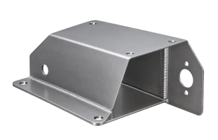
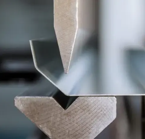
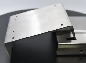
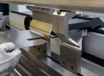
Bending This manufacturing process uses a dies to produce a U-shape 0.1-6mm
Get a Sheet Metal quote

Tolerances for sheet metal fabrication

Feature Tolerance
Cutting feature From ±0.0078"(0.2mm)
Bend angle From ±1.0°
Bend to edge From ±0.010"(0.254mm)

Available Materials for sheet metal fabrication

Material Type More Info
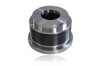
It is strong, which makes it ideal for mechanical parts, and its oxidized outer layer is resistant to corrosion from the elements.
Metal Get Quote
Excellent wear and corrosion resistance.
Metal Get Quote
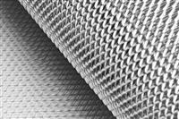
Since its carbon and alloying element content are relatively low, there are several properties it has that differentiate it from higher carbon and alloy steels.
Metal Get Quote
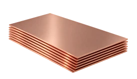
Strength, conductivity, corrosion resistance, machinability, and ductility make copper one of the most versatile materials for a broad range of applications.
Metal Get Quote
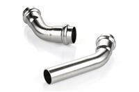
Advantages: lightweight, non-magnetic, resistant to salt spray and chloride ion corrosion, self-repairing surface passive film, and capable of TIG welding.
Metal Get Quote
The highest quality PMMA sheets are produced by cell casting, but in this case, the polymerization and molding steps occur concurrently.
Plastic Get Quote

Laser Cutting Design Guidelines

This guide is designed to help engineers and designers prepare CAD and vector files that meet laser cutting requirements. Following these design guidelines before order submission can help prevent file errors, improve cutting quality, shorten lead times, and reduce overall manufacturing costs.

1. File Formats & Submission Requirements

Select the appropriate file format based on your laser-cutting requirements.

Part Type Recommended Formats Use Case & Requirements
2D Vector .dxf, .dwg Recommended for flat laser-cut parts. Native vector files from Illustrator, Inkscape, or CorelDRAW are also accepted.
3D Solid .step, .stp, .iges, .igs, .sldprt Used when the part includes bends or forming and requires additional sheet-metal processing.

Unsupported Formats

  • Mesh Files: .stl, .obj, etc. are not accepted for flat laser cutting.
  • Raster Images: .jpg, .png, .tif, .bmp, etc. must be converted to vector geometry before submission.

2. Vector & CAD File Preparation

A production file should contain only the closed cutting geometry required to manufacture the part. Clean all construction elements and annotations before exporting.

Scale & Units

1:1 Scale: Build files at full final cut size. Written dimensions inside drawings are ignored by automated processing systems.

Units: Imperial (inches) is preferred. Metric (millimeters) is acceptable when used consistently between the file and quote. Centimeters and meters are not supported.

Manufacturing Geometry Only

Remove all dimensions, title blocks, borders, guides, notes, and annotations.
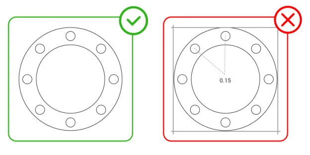
Manufacturing Geometry Only

Convert Text to Outlines

Convert all text to vector outlines (or explode/expand text in CAD). Editable fonts/text boxes cannot be recognized as cutting geometry.
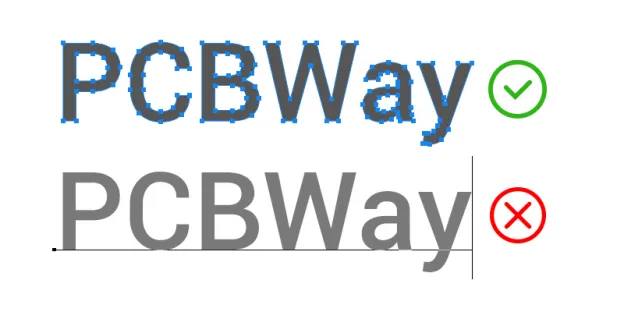
Convert Text to Outlines

Closed Cutting Profiles

Every cut path must form a fully closed shape. Inspect geometry in wireframe/outline mode before export to detect unclosed paths or tiny gaps.
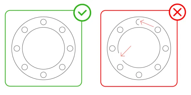
Closed Cutting Profiles

Duplicate & Overlapping Lines

Delete duplicate, overlapping, or intersecting vector entities. In multi-entity geometry, duplicated lines can be interpreted as double-cutting paths and ruin cut quality.
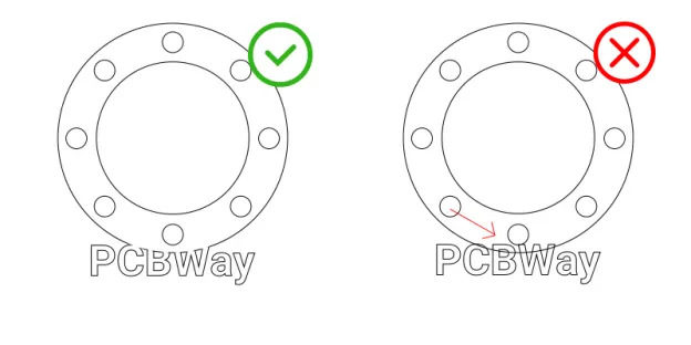
Remove duplicate and overlapping vector lines

Dedicated Layer Usage

Place all final cut paths on a designated cut layer. Move construction geometry or annotations to separate layers or delete them entirely prior to export.

Bridging Floating Interiors

Internal "islands" (e.g., the centers of letters like O, A, B, or donut-shaped cutouts) will become detached during cutting. Add bridges or stencil connections to retain them. Bridge width depends on material thickness.
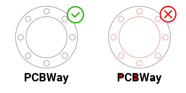
Add bridges to retain floating interior cutouts

3. Laser Cutting Feature Guidelines

Feature size, internal corners, spacing, and cutout density directly affect laser cutting quality. Check these elements against the requirements of your selected material and process.

Minimum Hole & Cutout Size

As a general guideline, the minimum hole or cutout diameter should be at least 50% of the material thickness.

Actual limits vary depending on material type, thickness, and laser cutting capability. Very small holes and intricate features may require engineering review before production.

Minimum Internal Radius

Internal corner size is affected by the material thickness and laser cutting process. Extremely small internal corners may not reproduce accurately.

Allow sufficient internal radius for the selected material and process, especially for small or tightly fitting features.
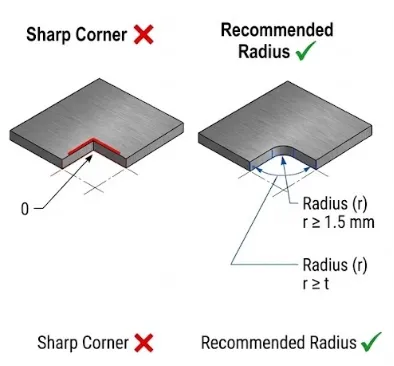
Minimum radius requirement for internal corners

Narrow Walls & Isolated Features

Extremely narrow walls, webs, and isolated features may distort or overheat during cutting.

Maintain sufficient feature thickness based on the material and cutting process. For thin materials, avoid long, narrow sections that can easily deform due to heat accumulation.
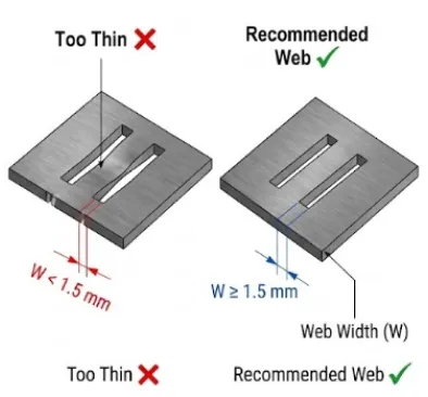
Avoid thin isolated features to prevent cutting distortion

Dense Cutout Patterns

Intricate patterns such as grilles, ventilation holes, and speaker grates increase cutting time and heat buildup.

For thin materials, increase the line or web thickness between cutouts if burn marks, discoloration, or deformation occurs during cutting.

Laser Kerf

Laser cutting removes a narrow amount of material along the cutting path, known as the kerf. Kerf width varies depending on the material, thickness, laser system, and cutting parameters.

Consider kerf when designing:

  • Tight-fit or mating components
  • Small holes and slots
  • Narrow gaps between adjacent features

For reference, typical cutting gaps may range from approximately 0.006″ to 0.012″, depending on material and process conditions.

Heat-Affected Areas

Laser cutting generates localized heat that can affect thin or heat-sensitive materials. Potential effects include edge discoloration, burn marks, localized deformation, and surface oxidation.

Avoid excessive concentrations of small features in a limited area, particularly when working with thin materials.

Part Spacing & Common-Line Cutting

Keep sufficient spacing between adjacent parts to account for laser kerf, heat accumulation, and process tolerances.

Do not share a cutting line between adjacent parts. Common-line cutting may affect dimensional accuracy and edge quality because kerf and heat input are not fully accounted for.

For multiple copies of the same part, upload one file containing a single part and set the desired quantity during checkout.

Directional & Mirrored Materials

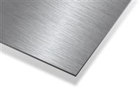
Materials with directional or decorative surfaces, such as brushed, mirrored, or textured sheets, may require a specific top/bottom orientation.

Save mirrored variations as separate files when surface direction matters.

Customer reviews about Sheet metal Service