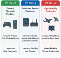
To ensure the proper functioning of electronic devices, X-ray inspection is performed on PCBs throughout the entire assembly process. Different categories of circuit boards have different inspection standards, and X-ray inspection is a widely adopted method that can detect defects that are not visible to the naked eye.
This article will provide a detailed introduction to automated X-ray inspection, including its workflow and benefits.
What is Automated X-ray Inspection?
PCB X-ray inspection, also known as automated X-ray inspection, is widely used in various industries, from medical to aerospace manufacturing, for identifying manufacturing errors. It is particularly common in PCB inspection because X-rays provide an excellent method for testing PCB quality and detecting hidden defects without damaging the circuit board.
The inspection system utilizes X-rays as the scanning source, which is suitable for detecting larger gaps and cracks. This method allows non-destructive access to the internal geometries and structural compositions. AXI (Automated X-ray Inspection) functions similarly to AOI (Automated Optical Inspection) by capturing images. The only difference is that AOI uses light sources, while AXI employs X-rays for scanning. All surface-mounted devices and their solder joints can be inspected using X-rays. The software on the machine can generate real-time 2D images of the components. With these images, defects can be easily visualized and analyzed, while the equipment can also identify the root cause of each issue.

How Does X-Ray Inspection System Work?
X-ray inspection works by measuring X-ray photons that pass through a given material. Different materials have different elemental compositions and corresponding atomic weights, and X-ray photons behave differently when interacting with certain elements. Heavier elements typically appear darker, while lighter elements appear more transparent, which finally results in dynamic X-ray images. Since PCBs are usually composed of heavier elements, detailed visual effects can be easily generated through X-ray imaging.
PCB X-ray inspection equipment typically consists of three basic components:
X-ray Tube: The X-ray tube is responsible for generating X-ray photons. Sometimes referred to as a Roentgen tube, the X-ray tube operates by accelerating electrons to high speeds and forcing them to collide with a target.
Sample Handling Platform: The platform of the X-ray machine is used to move the PCB sample in various directions, allowing X-ray inspection from all necessary angles.
Detector: The detector collects X-ray photons on the opposite side of the sample PCB and converts them into an image. This can be a 2D rendering or a detailed 3D image, depending on the specific software used.
Now, let's learn how AOI and X-ray work through the following video!
Advantages of X-ray Inspection
Capable of inspecting blind and buried vias: Vias are an important component of PCBs as they allow easy connectivity between different layers of signals. PCBs have different types of vias, including blind vias and buried vias. Inspecting these vias visually can be challenging, as they are difficult to detect. PCB X-ray machines emit radiation that can penetrate hidden and hard-to-reach points, enabling inspectors to easily assess the integrity of the holes and the quality of PCB connections and components.
Enables the visualization of BGAs: Ball Grid Array (BGA) is beneficial for component placement as it allows for smaller devices and the installation of tiny components on the PCB. However, BGAs still have their drawbacks, particularly in terms of quality assessment and inspection. BGA components are typically tightly encapsulated on the circuit board, leaving almost no space between installed components. This dense arrangement makes it difficult for inspectors to visually identify any defects in the PCB or the mounted components. PCB X-ray machines are often the best method for evaluating the quality of components and PCB connections, as X-rays can penetrate through BGA components. This non-destructive testing (NDT) allows inspectors to view individual components and identify any defects from the images generated by the PCB X-ray machine.
Identifies decoupling capacitor placement errors: Decoupling capacitors are crucial components in every electronic device as they ensure power stability and eliminate oscillations and transients. These capacitors are always connected in parallel with the power supply. Additionally, they are placed as close as possible to the power chips. However, incorrect placement of these capacitors can often lead to suboptimal device performance or even explosions that can harm users. Due to the tight installation of electronic components on PCBs, it can be challenging to detect errors in the connection solely through visual inspection. PCB X-ray machines enable inspectors to easily identify any misplaced components and correct the errors before the product is released.
Allows inspectors to see solder voids: Soldering is the method of connecting PCBs and components. If soldering is done incorrectly, faulty connections can occur, posing challenges to product quality. Furthermore, the product may not function optimally or even carry potential risks of harm to the user. To avoid these challenges, inspectors check for solder voids that may result in low-quality connections during the inspection. However, due to the dense arrangement of BGAs during installation, visual inspection may not satisfactorily examine the soldering conditions. PCB X-ray machines are often the preferred solution to address this challenge, as they enable inspectors to accurately detect solder voids that may lead to poor connection or product quality.
Easily identifies filled pin holes: One method of connecting components in a PCB is through plated through-holes. However, this connection often encounters certain defects, including filled pin holes. This problem is typically caused by gas escaping during soldering, with the gas usually being water vapor. If excessive heat is applied during soldering, the pin holes can become filled, leading to continuous gas escape. Identifying these anomalies using visual inspection or other inadequate means can often be challenging. However, PCB X-ray machines provide the best method for identifying filled pin holes during the quality assessment, ensuring the integrity of soldering operations.
As one significant improvement in AXI, automated X-ray inspection, not only are 2D techniques available, but machines utilizing 3D technology are available and give significant improvements in performance. For 3D AXI equipment, PCBWay uses model Xscan-7130, it has a high-efficiency Inspection system also it has secured the best stability and safety in the industry (amount of surface leakage less than 1μsv/h).
To know the inspection coverage of AXI clearer, the table below as reference.
DEFECT TYPE | AXI |
Soldering defects |
Open circuits | Y |
Solder bridges | Y |
Solder shorts | Y |
Insufficient solder | Y |
Solder void | Y |
Excess solder | Y |
Solder quality | Y |
Component defects |
Lifted lead | Y |
Missing component | Y |
Misaligned or misplaced component | Y |
Incorrect component value | N |
Faulty component | N |
BGA and CSP defects |
BGA shorts | Y |
BGA open circuit connections | Y |