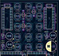
In today's context, a small PCB can potentially contain thousands of solder joints and numerous tiny components. The increased complexity leads to higher possibilities of errors. When standard visual inspections are insufficient to detect minute defects in densely packed circuit boards, technologies like Automated Optical Inspection (AOI) aid in providing deeper insights and accuracy.
What is AOI?
Automated Optical Inspection (AOI) is a visual quality control method used to identify defects that may occur during the manufacturing and assembly stages of PCBs. In this technology, cameras scan the circuit board to inspect various surface feature defects such as stains, scratches, open circuits, and short circuits. Additionally, it can also identify missing, incorrect, or improperly placed components.
PCB manufacturers will pass the PCB through AOI equipment after all components have been placed and then run it again after the soldering is completed. Throughout the process, the cameras capture multiple images that are used to generate a standard, often referred to as a golden standard, which represents a successfully assembled circuit board.
During subsequent production runs, AOI scans new images and compares them to the existing golden standard. When it encounters areas that do not meet the standard, it identifies potential defects in those areas. Later, technicians identify these errors and find possible solutions to correct them.
Now, let's explore AOI together through a video!
How Does AOI Work?
AOI systems utilizes lighting, machine vision cameras, high-resolution images and processing software.
Visual inspection lighting
Proper lighting of components is a prerequisite for AOI systems. This is because it requires a clear view to verify the characteristics of different parts. Previously, AOI machines used different types of lights such as incandescent lamps, fluorescent lamps, infrared, and ultraviolet lights. However, modern machines now utilize LEDs as light sources,the lighting system consists of configurable lighting modules with red, white, green, and blue LEDs, which provide uniform and consistent illumination.
The lighting angle is also crucial. During the PCB assembly process, the light may be blocked by taller components, preventing it from reaching shorter components. Some features require very low lighting angles, so the AOI system must have light sources from different angles to provide optimal overall illumination.
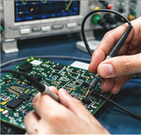
Machine Vision Camera
An automated optical inspection camera captures images of the product and evaluates them using processing software in an AOI machine. The range of cameras used in modern equipment varies from extended graphics array (XGA) to high-resolution sensors with millions of pixels, and the latest cameras can even achieve up to 100 frames per second (fps), demonstrating the efficiency of AOI in generating large amounts of data.
• Optical system resolution: In automated optical inspection, the resolution of the optical system is crucial as it determines the range of details visible to AOI. Key factors affecting system resolution include detection speed, accuracy, the size of the smallest components on the circuit board, the camera's sensor, lens, and the distance to the circuit board.
• Field of view: The FOV is defined by the resolution of the camera sensor and refers to the area of the board that a single image can cover. A wider field of view allows scanning the circuit board with fewer images and at a lower frame rate. Conversely, a narrower field of view has a higher frame rate.

AOI Processing Software
Product specifications or acceptable standards need to be inputted into the AOI system, which serves as a reference (golden standard) during the inspection process.
There are two methods:
• Golden board method: The automated optical inspection machine selects a qualified product and scans it through various stages, generating a golden standard that is used for further production.
• Algorithm-based programming: The AOI system generates a profile of the product by importing product data or specifications.

The Advantages and Disadvantages of AOI
Advantages:
Disadvantages:
Limited flexibility in defect detection, and programming is required for every change.
AOI does not identify new defects, it only detects pre-programmed defects.
AOI only captures PCB defects and does not capture defects with difficult-to-classify failure modes, such as adhesive or sealing defects.
The team does not have access to the data from the AOI system.
It is typically unable to remotely program new defect tests into the AOI system.
AOI does not provide value in terms of development.
Applications of AOI
AOI has extensive applications in the electronics manufacturing industry:
PCB inspection: AOI can be used for the inspection of bare boards (PCBs without assembled components) to check for issues such as solder pads, soldering quality, circuit connectivity, etc. It helps quickly identify and rectify defects during the manufacturing process, ensuring the quality and performance of the circuit boards.
SMT (Surface Mount Technology) inspection: AOI is commonly used on SMT assembly lines. It can inspect correct component placement, position offset, polarity errors, pin shorts, and other issues. This helps improve assembly quality and reduces the workload of manual inspection.
Welding quality inspection: AOI can inspect the quality of soldered connections, including solder pad quality, solder volume, soldering defects, etc. It performs inspections by image processing and comparing against expected standards to ensure the reliability and performance of soldered connections.
Defect detection and classification: AOI can detect and classify various defects such as shorts, opens, excessive soldering, component misplacements, etc. This helps in early detection and resolution of issues during the manufacturing process, improving product quality and consistency.
Barcode reading and traceability: AOI can read and identify barcode information on electronic products, including product serial numbers, batch numbers, production dates, etc. This helps trace the manufacturing and assembly process of products and provides capabilities for quality tracking and traceability.
From AOI inspection results, the following information can be obtained: