
Prototype de PCB en toute simplicité

Service complet de prototypage de PCB personnalisé.

Tapping sizing and options

Part Sizes

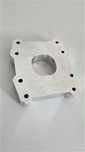
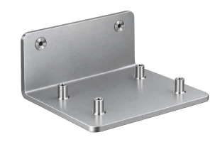
Tapping creates internal threaded holes within metal workpieces for screw assembly. Manual tapping is applicable for large format flat sheets within certain dimensional limits, while thread quality relies on proper hole to edge clearance matched to thread specifications.

  • Max thread hole:
    M18
  • Min thread hole:
    M1
  • Min flat part dimension:
    50 × 50 mm
  • Max flat part dimension:
    3000 × 1500 mm
  • Min flat part dimension:
    Dependent on thread specification

Three threading options · matched to your needs

Fast · Consistent
Machine Tapping
Machine Tapping Automated tapping creates precise internal threads using tap tools driven by machine spindles. It delivers reliable thread geometry and saves manual labor, well suited for standardized high volume manufacturing scenarios.
  • Suitable for CNC-machined parts.
  • Consistent thread quality.
  • Ideal for production runs.
  • High efficiency internal thread generation.
Fast · Consistent
Machine Tapping
Machine Tapping Automated tapping creates precise internal threads using tap tools driven by machine spindles. It delivers reliable thread geometry and saves manual labor, well suited for standardized high volume manufacturing scenarios.
Flexible · Complex
Thread Milling
Thread milling provides greater flexibility for different thread sizes and materials, especially for larger or more complex threads.
Reinforced · Durable
Tapping + Thread Inserts
Thread inserts reinforce tapped holes in softer materials or applications requiring repeated assembly and disassembly.

Available Materials For Tapping

In addition to the materials listed below, we also accept customer-supplied materials for processing.

Our Surface Finishes For Tapping Parts

With our precision tapping capabilities, machined parts gain accurate, reliable internal threads,
built to ensure secure fastening and consistent assembly performance.

Standard (As-Milled) (Ra 125μin)
The finish option with the quickest turnaround. Sharp edges and burrs would be removed by default. (If you need parts with sharp edges and burrs, please remark below or note on 2D drawing). Surface finish is comparable to 125 uin Ra finish.
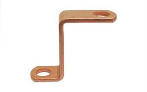
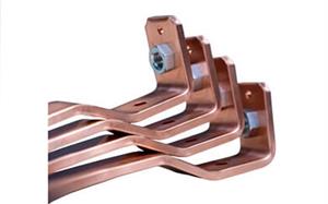
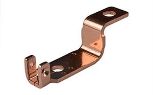
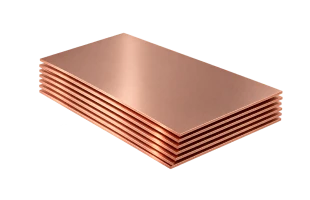
  • Copper C110
  • Stainless steel 304
  • Aluminum 5052
  • Copper 260 (Brass)

Standard (As-Milled) (Ra 125μin)

Bead blast + Anodized color

Anodized

Electrically conductive oxidation

Black oxide

Brushed

Tapping Capability

Process Description
Max thread hole M18
Min thread hole M1
Min flat part dimension for tapping 50 × 50 mm
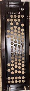
Max flat part dimension for manual tapping 3000 × 1500 mm
Minimum hole to edge distance for tapping Dependent on thread specification

Sheet Metal Tapping Design Guidelines

This guideline aims to provide structural engineers and mechanical designers with Design for Manufacturability (DFM) specifications for thread tapping in sheet metal fabrication and CNC milling/turning processes. It helps designers effectively avoid tool chipping, thread stripping, bend deformation, and engineering question (EQ) delays during the design phase—thereby significantly improving the automated DFM review approval rate, eliminating redundant back-and-forth communication, and substantially reducing order lead times and processing schedules.


1. Key Sheet Metal Tapping Parameters

In sheet metal cutting and CNC machining, tapping is a critical process that creates internal threads in pre-machined pilot holes to allow direct fastening with bolts and screws. Compared to traditional methods like adding clinching nuts (PEM Nuts) or using clearance holes with standard nuts, direct tapping significantly reduces the bill of materials (BOM), lowers assembly labor, and achieves exceptional surface flatness.

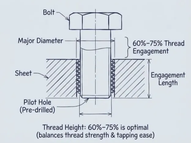
  • Thread Engagement: The percentage of overlapping profile depth between the external and internal threads. Thread engagement directly determines the pull-out strength of the threaded connection and the difficulty of machining.
  • Thread Pitch: The axial distance between corresponding points on adjacent thread teeth. Metric threads express this as pitch in millimeters (e.g., M4 × 0.7), while Imperial threads express it as threads per inch (TPI, e.g., 1/4-20).
  • Tap Drill Size (Pilot Hole Diameter): The pre-drilled or laser-cut hole diameter prior to tapping. An undersized hole can cause tap breakage or binding, whereas an oversized hole results in insufficient thread height and stripped threads.


2. Thread Engagement & Geometric Calculations

When designing tapped parts, avoid blindly striving for 100% thread height. Research and engineering practice demonstrate that a thread engagement of 60% to 75% provides 100% of the bolt's ultimate tensile strength; further increasing engagement exponentially increases cutting torque and tap breakage risks.

Thread Engagement Formula

Thread Engagement (%) = [ (D_major - D_hole) / (1.08253 × P) ] × 100%

(Note: Major Thread Diameter D_major and Pilot Hole Diameter D_hole are in mm; Pitch P is in mm)

Recommended Thread Engagement by Material

  • Soft Materials (Aluminum 6061-T6, Copper, Engineering Plastics POM/PA): A 70% to 75% thread engagement is recommended to achieve higher shear strength.
  • Hard Materials (Stainless Steel 304/316, Carbon Steel, Titanium Alloys): A 50% to 60% thread engagement is recommended to significantly reduce tool wear and work-hardening risks.

Sheet Thickness to Engagement Depth Ratio

The optimal effective thread engagement length should reach 1.0 to 1.5 times the nominal bolt diameter (e.g., the effective depth for an M4 thread should be between 4 mm and 6 mm). For thin sheet metal where the plate thickness is less than 1.0 times the thread diameter, extruded/flanged hole tapping processes can be used to extend engagement depth.


3. Sheet Metal vs. CNC Machining Tapping Guidelines

Laser-cut sheet metal and solid CNC machined parts differ fundamentally in tapping processes and must follow distinct geometric constraints:


4. Core Sheet Metal Tapping DFM Rules

Clearance from Bends and Features

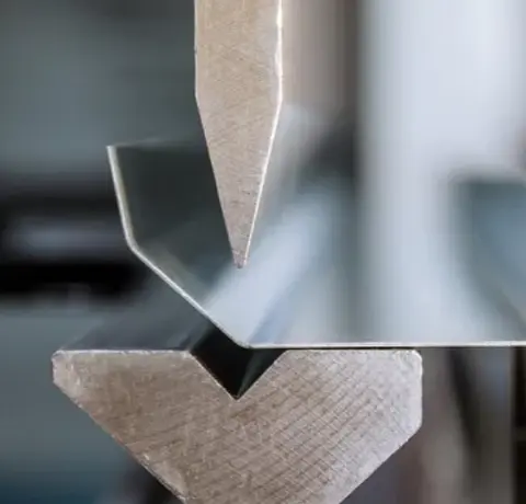
When placing tapped holes near sheet metal bend lines, tensile stresses during bending cause thread distortion, preventing proper bolt insertion.

  • Bend Clearance Rule: The distance from the tapped hole center to the bend line must be ≥ (1/2 × Bend Die Opening Width + 2 × Sheet Thickness).
  • Feature Clearance Rule: Tapped hole edges must maintain a distance of at least 1.5 × Sheet Thickness from other cut features (e.g., large cutouts, slots).

Tool Clearance and Fixture Interference

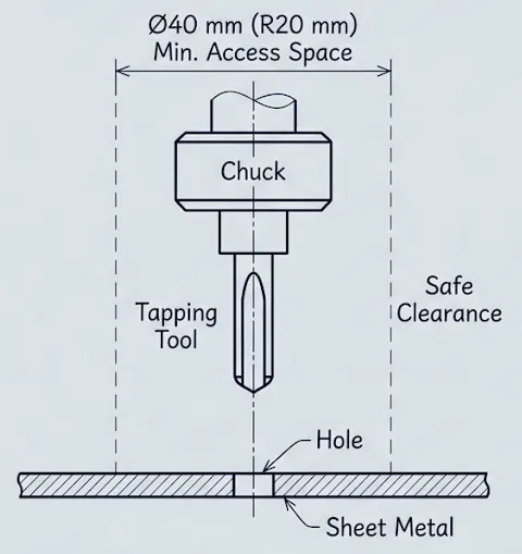
Automated tapping machines and CNC tapping heads require adequate clearance. If a tapped hole is close to high vertical walls or internal cavity corners, the tapping chuck will collide.

  • Geometric Interference Warning: Ensure a cylindrical clearance area above the tapped hole axis with a radius of at least 20 mm and no height obstructions to allow unhindered spindle entry.
  • Heat-Affected Zone (HAZ) & Thermal Expansion Compensation Strategy: Laser cutting creates a micro-hardened layer (HAZ) along the hole wall. To prevent this hardened layer from breaking taps, for aluminum alloys and carbon steel, it is recommended to enlarge the pilot hole in the CAD model by 0.05 mm to 0.08 mm (0.002" to 0.003") over standard pre-drilled sizes to compensate for thermal expansion, contraction, and tool wear.


5. Recommended Sheet Metal Tapping Drill Size Chart

The table below lists common metric and imperial tap sizes along with their recommended pre-drilled hole diameters in 2D/3D models:


6. CAD File Preparation

  1. Model Setup: In 3D CAD (STEP) or 2D (DXF), do not model physical thread geometry! Draw smooth, plain cylindrical pilot holes. Modeling physical 3D threads causes CAM toolpath parsing errors.
  2. Diameter Identification: Set the hole diameter to be tapped to the target thread's nominal major diameter or standard tap drill size. Upon cloud system upload, intelligent algorithms will automatically identify and prompt tap assignment.
  3. Surface Finish Margins: If the part requires subsequent anodizing or powder coating, specify in advance on order notes: "Tap before anodizing" or request thread masking.


7. Pre-Manufacturing Checklist
  • File Format Verification: 2D submitted in .dxf or .dwg (1:1 scale, free of overlapping or broken lines); 3D submitted as a single solid .step / .stp file.
  • Smooth Pilot Holes: All holes intended for tapping are plain smooth cylinders without helical curves or 3D thread meshes.
  • Thickness-to-Depth Ratio: Sheet metal thickness meets effective engagement requirements (if plate thickness < 1× Thread Diameter, PEM nuts or extruded tapping have been evaluated).
  • Edge & Bend Clearance: Hole center to edge ≥ 2.0× Thread Diameter; hole center to bend line ≥ (1/2 × Die Opening Width + 2 × Sheet Thickness).
  • Blind Hole Clearance (CNC): For CNC blind holes, the total drill depth extends at least 3× Pitch (3P) beyond the effective thread depth for chip relief.
  • Perpendicularity Confirmation: All tapping axes are strictly perpendicular to their respective faces.

Customer Reviews

Frequently Asked Questions

What is tapping used for?

Tapping creates internal threads inside a drilled or machined hole, allowing screws, bolts, and other threaded fasteners to be securely installed.

Can you tap blind holes?

Yes. Blind holes can be tapped to a specified thread depth, provided sufficient clearance is allowed at the bottom of the hole.

How should I design a tapped hole?

Specify the thread size, thread standard, thread depth, hole depth, and whether the hole is blind or through. Adequate space should also be provided around the hole for tooling access.

What thread standards do you support?

Common metric and imperial thread standards can be supported, including M-series, UNC, and UNF threads. Specific thread availability depends on the required size and material.

What materials can be tapped?

Tapping can be performed on materials such as aluminum, steel, stainless steel, brass, copper, and engineering plastics. The appropriate tooling and cutting parameters vary by material.

Your files are in safe hands with us.
Start producing your project right away.

Get in touch with our team. Call us directly on. Or email us at 3dcnc@pcbway.com

Get instant quote

Full manufacturing capability at your fingertips