


WS2812B RGB LED Controller with ESP8266 via WiFi
Introduction
WS2812b addressable RGB LEDs are devices widely used in lighting projects. They are found in the format of LED matrices and strips.
LED strips, for example, are widely used in decorative lighting, luminaire construction and many other applications.
And to ensure the correct color, it is necessary to use a controller to control the color, luminous intensity and lighting effects of the LEDs.
Most WS2812B LED controllers use a remote control. However, our goal is to develop a controller that can receive these control commands over WiFi with a cell phone application.
Therefore, in this article we will develop a controller with ESP8266 along with WLED firmware. This firmware consists of a cell phone application and the user can register several controllers in the same application. This makes the system simple and makes it easier to control multiple lighting points from a single location.

Next, we will present the electronic schematic of the project and the explanation of each block of the electronic circuit.
Circuit Design of the WS2812B LED Controller
Below we present the electronic schematic of the controller. It consists of 6 circuit blocks.

The circuit for this controller is quite simple. We will start the explanation from the power connectors and LEDs circuit.
Power Circuit Connectors and LEDs
The project circuit is powered with +5V. This voltage will be used to power the LED circuit and used in the voltage regulator input circuit for the ESP8266.

After the connector circuit, we have the voltage regulator circuit.
Regulator Circuit Voltage +3V3
The AMS1117 voltage regulator circuit has the purpose of regulating the voltage to supply the ESP8266 circuit with +3V3. The electronic schematic is presented below.

From the voltage regulator circuit, we can power the ESP8266 circuit.
ESP8266 Circuit
This circuit is composed of the basic ESP8266 configuration circuit, the buttons to configure the ESP8266 in programming mode and the programming pins.

The first circuit has the basic operating configuration of the ESP8266. The Reset and Flash buttons are responsible for putting the ESP8266 into programming mode. To perform the code transfer, you must use a USB-TLL converter and connect it to pins +3V3, TX, RX, and GND, as shown in the programming pin circuit.
After creating the electronic schematic, the following layout of this printed circuit board was obtained. From this circuit, it is possible to control the WS2812B LEDs.

There are two ways to control them with the ESP8266. You can use WLED firmware or WS2812FX library (Arduino IDE).
In this project we will use the WLED library. It consists of a firmware and an application. Through the app you can register several devices on your WiFi network and control them through your cell phone.
The WLED application for controlling addressable RGB LEDs
WLED is a system with several features that allows us to control different types of addressable RGB LEDs through a web server with ESP8266/ESP32. Among these LEDs, we have the WS2812B, which will be the LEDs that we will control in our application.
To use this system, you need to create lines of code to control the LEDs, as there is already a firmware ready to be installed and connect your driver to the WiFi network through an application or web page made available by the community.
The control page can be accessed via cell phone or computer.
Now let's move on to the stage of installing the WLED firmware on the controller.
How to install WLED firmware on ESP8266?
The WLED installation process is very simple. You need to access the website to start the process of transfer the firmware to your electronic board. After accessing the website, put your ESP8266 in programming mode using the Flash and Reset buttons and, after that, click Install to start the firmware transfer.

Now you must configure your WiFi network data in the controller settings. This will be necessary for you to be able to register your electronic license. Install the WLED application on your cell phone. It is available for free for Android and IOS.
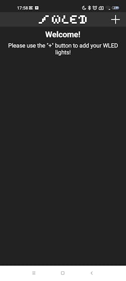
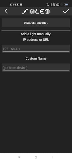
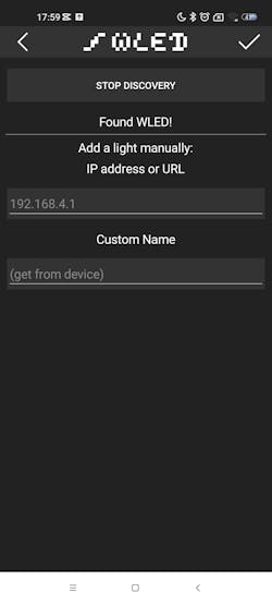
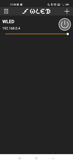
After installing the application, you must follow the steps shown in the images above to scan the WiFi network, detect your controller and register it in the control application.
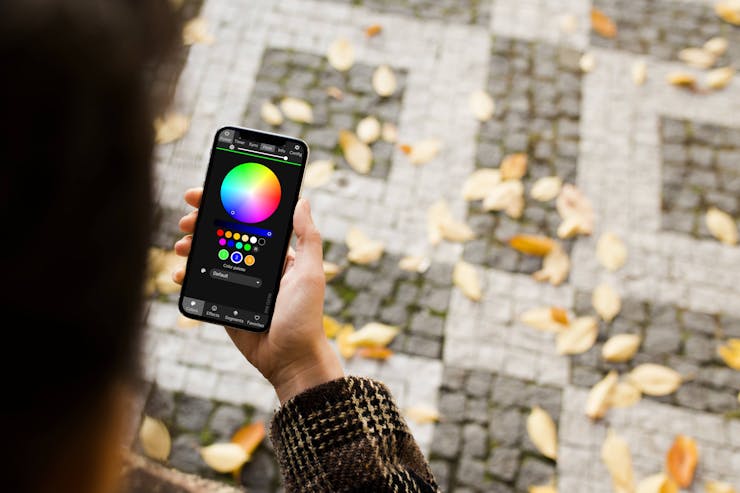
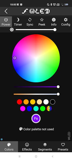
On the last screen it is possible to observe the color control environment, light intensity and effects for the LEDs.
Project Results
Below we have images of the RGB LEDs being controlled via the WiFi controller with WLED firmware. We selected 3 different colors to show the result.


As you can see, the system worked with satisfactory results and you can place your Addressable RGB LED strip or matrix to be controlled via WiFi.
Acknowledgments
We would like to thank PCBWAY for supportting the creation of this project and made some units available for you to earn for free and receive 5 units at your home. To receive them, access this link, create an account on the website and receive coupons for you to win right now.
WS2812B RGB LED Controller with ESP8266 via WiFi
*PCBWay community is a shared platform and we are not responsible for any design issues.


- Comments(0)
- Likes(0)
More by silicioslab
-
 WS2812B RGB LED Controller with ESP8266 via WiFi
IntroductionWS2812b addressable RGB LEDs are devices widely used in lighting projects. They are foun...
WS2812B RGB LED Controller with ESP8266 via WiFi
IntroductionWS2812b addressable RGB LEDs are devices widely used in lighting projects. They are foun...
-
 Electronic Board for Cutting Electrical Power to Devices and Machines
IntroductionAn energy saving system for cutting electrical energy in machines is a fundamental piece...
Electronic Board for Cutting Electrical Power to Devices and Machines
IntroductionAn energy saving system for cutting electrical energy in machines is a fundamental piece...
-
 PCB Board Home Automation with ESP8266
IntroductionThe incorporation of the ESP8266 module into home automation represents a significant ad...
PCB Board Home Automation with ESP8266
IntroductionThe incorporation of the ESP8266 module into home automation represents a significant ad...
-
 Dedicated Control Board for Mobile Robots with Wheels
IntroductionFor a long time we developed several prototypes and teaching kits of mobile robots and w...
Dedicated Control Board for Mobile Robots with Wheels
IntroductionFor a long time we developed several prototypes and teaching kits of mobile robots and w...
-
 Traffic turn signal for bicycles
IntroductionDoes every project with electronic logic need a Microcontroller or Arduino to be develop...
Traffic turn signal for bicycles
IntroductionDoes every project with electronic logic need a Microcontroller or Arduino to be develop...
-
 Mini Arduino with ATTINY85
Do you know the ATTINY85 microcontroller? This article has news and a gift for you. Many people deve...
Mini Arduino with ATTINY85
Do you know the ATTINY85 microcontroller? This article has news and a gift for you. Many people deve...
-
 Christmas Tree
The tree used to signal light of Christmas.
Christmas Tree
The tree used to signal light of Christmas.
-
 Activating loads with relay via WiFi with ESP8266
IntroductionDo you want an electronic board for activating loads via WiFi that is safe against surge...
Activating loads with relay via WiFi with ESP8266
IntroductionDo you want an electronic board for activating loads via WiFi that is safe against surge...
-
 Hospital Water Tank Monitoring via the Internet
IntroductionOne of the elements of great importance for the functioning of hospitals is water. It is...
Hospital Water Tank Monitoring via the Internet
IntroductionOne of the elements of great importance for the functioning of hospitals is water. It is...
-
 ESP32 IoT Development Board with Monitoring Battery System
IntroductionToday I want to tell you what one of the biggest problems is in electronic projects invo...
ESP32 IoT Development Board with Monitoring Battery System
IntroductionToday I want to tell you what one of the biggest problems is in electronic projects invo...
-
 Control Board for 6 Servomotors based on Arduino for Robotic projects
In the last few weeks we started developing this robotic arm. It is made up of 5 servomotors. To fac...
Control Board for 6 Servomotors based on Arduino for Robotic projects
In the last few weeks we started developing this robotic arm. It is made up of 5 servomotors. To fac...
-
 PCBWay Standalone Arduino
IntroductionDo you know how the basic circuit of an Arduino works? Every Arduino has a minimum circu...
PCBWay Standalone Arduino
IntroductionDo you know how the basic circuit of an Arduino works? Every Arduino has a minimum circu...
-
 Human Machine Interface based in Arduino with ATMEGA328P Standalone
Several commercial and industrial applications require a screen system to present data and receive p...
Human Machine Interface based in Arduino with ATMEGA328P Standalone
Several commercial and industrial applications require a screen system to present data and receive p...
-
 Small Low Cost Circuit Deveelopment Board for Prototypes
In recent years I have developed numerous prototypes with Arduino. During these creations, something...
Small Low Cost Circuit Deveelopment Board for Prototypes
In recent years I have developed numerous prototypes with Arduino. During these creations, something...
-
 Intruder alert system with SMS
In several places, we must monitor the security of spaces and prevent intruders from entering prohib...
Intruder alert system with SMS
In several places, we must monitor the security of spaces and prevent intruders from entering prohib...
-
 Mini Arduino Laboratory
I have worked in teaching laboratories for over 10 years. One of the great difficulties in these spa...
Mini Arduino Laboratory
I have worked in teaching laboratories for over 10 years. One of the great difficulties in these spa...
-
 PCBWay WiFi ESPBoard-01
Can you imagine controlling any device over the internet? Lamps, water pumps for irrigation, gate dr...
PCBWay WiFi ESPBoard-01
Can you imagine controlling any device over the internet? Lamps, water pumps for irrigation, gate dr...
-
 Educational Robot for Children
All areas of knowledge such as sciences, human or biological, have their respective importance. With...
Educational Robot for Children
All areas of knowledge such as sciences, human or biological, have their respective importance. With...
-
-
Open Source Very Large Stick - Freejoy & MMjoy2 breakout board
560 0 0 -
RF Control training board for students based on ESP32 C3
741 0 2 -
-
KINETIC COASTERS with a TWIST! Laser or 3D Print some DIY Magic
643 0 1 -
RPI - 8 IO PLC With ATTiny85 Watch Dog
556 0 1 -
Nintendo Famicom HVC-001 Controller Shells
665 0 1 -
COMMODORE 128 DIAGNOSTIC REV.785260 KEYBOARD DONGLE
620 0 4


