


Voltage Controlled Multimode Resonant Filter
After getting my hands dirty with a linear Power Supply for my modular, it was time to develop a PCB for what I consider the most importan part of a synthesizer: the filter!
In the following I will show you the filter I have choosen for my synth and describe the PCB I have designed.
I will also share a link to have the PCB manufactured by professionals at a good price.
Circuit and Components Selection
During the glory days of analog synthetizers manufacturers fought their war developing original (and sometimes not-that-original) circuits for their products. What is left are incredibly expensive synthetizers, but also precious schematics which constitute a great source to get inspiration from, or even (respectfully) clone circuits.
One of my favourite filters is the one Korg developed for the MS20. In particular, I must admit that I have a soft spot for the so called "Mark II" filter because less aggressive than the Korg35 module and more suited to my musical tastes (shame on me).
There are various projects developed around that filter out there, and I had to notice the work of René Schmitz and especially Kassutronics on this regard. In this project, I wanted to keep the filter as similar to the Korg MS20 MKII as possible, using components most resembling those used by Korg and givin up others improvements to it, where possible. I am aware that a subtractive approach is easier than the opposite, so credits goes to Renè and Kassu for their shared work.
The filter here presented clones the original Korg MS20 MK II multimode resonant filter. As per Korg schematics, the active components are LM13600 Dual Operational Transconductance Amplifiers (OTA), some generic amplifiers in buffer configuration at the LM13600 output and a JRC4558 dual op-amp in the feedback circuit. A dual PNP transistor in single package (A798F) serves the main circuit takeing care of the CV tracking.
These components are mostly obsolete, but there are very good replacements availabe. The LM13700 is a direct replacement for 13600 and high performane amps, specifically designed for audio applications like the NE5532 are the obvious choice as buffers in the audio path.
Feedback and especially CV track circuit are less prone to give audio interference, so it is possible to use a more generic (noisy) op amp like TL072. I made some testing and, honestly, could not hear any difference by using NE5532 in place of the TL072.
The A798F in the exponential converter circuit is replaced by two BC557.
I used yellow LEDs to emulate the presence of three diodes and get a voltage drop in the range of 2.1-2.2V. You can use a different color (i.e. green or even blue) if you want a more "wild" behaviour from the feedback loop.
Warning: the filter goes wild (very very loud and eventually highly pitched) when the resonance is set "too high" and the filter starts self-oscillating. Keep the resonance pot at moderate levels or damage to your ear and/or equipment could occur.
Low Pass or High Pass - You Choose!
A welcome characteristic of this filter design is the possibility to switch from a high pass mode to a low pass mode simply by changing the input of the incoming audio signal. The Korg MS20 was equipped with a high pass resonant filter followed by a low pass resonant filter (see previous step).
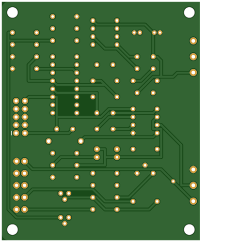
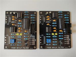
The PCB I have developed takes this into consideration, and the fact that PCB manufacturers give you multiple of 5 PCBs. So, instead of developing a bigger, double LP+HP filter, you can easily populate two PCBs, and set the two to different modes.
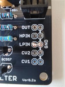
High Pass mode can be set by short circuiting to ground the low pass input (LP_IN) and feeding your audio source to high pass input (HP_IN).
Low Pass mode can be set by shorting the high pass input (HP_IN) to ground and input audio to LP_IN.
I placed ground pads all over the PCB: it's your choice to use one pad per jack connector or daisy chain grounds directly on connectors.
BOM
Follows the list of components for the filter:
Capacitors
- 1x 4.7nF poly capacitor
- 2x 1nF poly capacitor
- 3x 100nF poly capacitor
- 1x 470nF poly capacitor
- 2x 100u electrolitic capacitor
Amplifiers and Transistors
- 1x NE5532 audio amplifier
- 1x LM13700 dual OTA
- 1x TL072 operational amplifier
- 2x BC557 PNP transistor
Resistors
- 3x 4.7K ohm
- 4x 220 ohm
- 1x 220K ohm
- 6x 10K ohm
- 1x 1.5K ohm
- 2x 1K ohm
- 1x 470K ohm
- 2x 100K ohm
Others
- 1x IDC connector (2x5 pin)
- 2x LED (3mm, yellow)
- 1X 10K potentiometer (linear)
- 1X 100K potentiometer (linear)
- 1X 1N4004 diode
Please, notice that the filter pictured is my prototype and doesn't have an inverse polarity protection diode. The version shared actually is voltage protected against +12V and -12V invertion. It's also slightly rearranged in some relative distance between components.
Voltage Controlled Multimode Resonant Filter
*PCBWay community is a shared platform and we are not responsible for any design issues.


- Comments(0)
- Likes(4)
More by Marco Guidolin
-
 Arduino Voltage Controlled Wavetable Oscillator
Lurking for a simple digital filter for my modular synthesizer, I got aware of the existence of a li...
Arduino Voltage Controlled Wavetable Oscillator
Lurking for a simple digital filter for my modular synthesizer, I got aware of the existence of a li...
-
 Kurzweil K1000 K1200 Display Replacement PCB
IntroductionThe Kurzweil K1000 is a classic synthesizer series that was produced from 1988 to 1992. ...
Kurzweil K1000 K1200 Display Replacement PCB
IntroductionThe Kurzweil K1000 is a classic synthesizer series that was produced from 1988 to 1992. ...
-
 Variable Waveshape Low Frequency Oscillator
One of those modules you should want in your arsenal when starting a "DIY modular adventure" is the ...
Variable Waveshape Low Frequency Oscillator
One of those modules you should want in your arsenal when starting a "DIY modular adventure" is the ...
-
 Discrete Voltage Controlled Amplifier
Together with the Power Supply Unit, Voltage Controlled Resonant Filter and ADSR, another modular's ...
Discrete Voltage Controlled Amplifier
Together with the Power Supply Unit, Voltage Controlled Resonant Filter and ADSR, another modular's ...
-
 Arduino ADSR Digital Envelope Generator
It's incredible how many things you can accomplish with (as per today standards) tiny processors lik...
Arduino ADSR Digital Envelope Generator
It's incredible how many things you can accomplish with (as per today standards) tiny processors lik...
-
 Voltage Controlled Multimode Resonant Filter
After getting my hands dirty with a linear Power Supply for my modular, it was time to develop a PCB...
Voltage Controlled Multimode Resonant Filter
After getting my hands dirty with a linear Power Supply for my modular, it was time to develop a PCB...
-
 BA8 - Power Bus Bar
While designing the Linear Power Supply PCB, I forced myself to keep dimensions within the 10 cm x10...
BA8 - Power Bus Bar
While designing the Linear Power Supply PCB, I forced myself to keep dimensions within the 10 cm x10...
-
 ALR350 - DIY Linear Regulated Eurorack Power Supply
Modular synthesizers are extremely attractive objects. With the right selection of modules, they giv...
ALR350 - DIY Linear Regulated Eurorack Power Supply
Modular synthesizers are extremely attractive objects. With the right selection of modules, they giv...
-
 ArcadeHID - Multi HID Interface for Arcade Projects
IntroductionIf you are an arcade enthusiast you surely know how important is to have the right perip...
ArcadeHID - Multi HID Interface for Arcade Projects
IntroductionIf you are an arcade enthusiast you surely know how important is to have the right perip...
-
 Korg PME40X External Selector "Clone"
DIY Korg PME40X External Selector "Clone"I am a PME40X user, and I like this multi effect very much....
Korg PME40X External Selector "Clone"
DIY Korg PME40X External Selector "Clone"I am a PME40X user, and I like this multi effect very much....
-
 CompuLab - a DEC H500 Inspired Logic Trainer
CompuLab is a simple logic trainer I designed as a labour of love for one of those "ancient" pieces ...
CompuLab - a DEC H500 Inspired Logic Trainer
CompuLab is a simple logic trainer I designed as a labour of love for one of those "ancient" pieces ...
-
 Arcade Jamma Prototypes Development Board
Contrary to what one would expect, the Arcade world is not dead but growing thanks to thinkerers com...
Arcade Jamma Prototypes Development Board
Contrary to what one would expect, the Arcade world is not dead but growing thanks to thinkerers com...
-
Commodore 1551 Drive Cartridge Replacement
64 0 2 -
-
-
(DIY) COMMODORE 64 DEAD-TEST (781220) DIAGNOSTIC CARTRIDGE
310 0 2 -
Creative Micro Designs Inc. CMD FD-2000 / FD-4000 3D Printable Case
359 0 0 -
Creative Micro Designs Inc. CMD FD-2000 / FD-4000 Metal Case
522 0 0 -


